DJC.COM
January 18, 2007
Engineering the path took a lot of twists and turns
Magnusson Klemencic Associates

Gangnes
|
Seattle’s Olympic Sculpture Park is a visionary architectural achievement blending building and site design to an extent few projects achieve or even attempt. Luckily, the Seattle Art Museum recognized the genius of Weiss/Manfredi’s concept of a strollable park on Seattle’s steep waterfront, since the built form is virtually identical to the original inspiration.
Weiss/Manfredi engaged the team to design a “building/site system,” starting with a vision of folds of earth that guide a visitor’s journey down a continuously sloping, 2,200-foot-long Z-path, revealing artwork along the way. The “how” part of the engineering was secondary: “This is where the land needs to cross the street — now let’s design a bridge to achieve that.”
Examples of the fruits of this collaboration follow.
A soil-rentention twist
For the architect’s Z-path vision to be successful, a 50-foot elevation change had to feel effortless, and two bridge crossings needed to virtually disappear into their surroundings. There was only one problem: the entire length of the proposed path hovered in mid-air, up to 32 feet above the existing grade!

Images courtesy MKA A conventional mass-concrete approach for the park’s retention system (left) would have proven costly and difficult to build on the site’s settlement-prone soils. Engineers opted instead for a mechanically stabilized earth system with custom fascia. |
Some 215,000 cubic yards of dirt (equivalent to a 100-foot-deep, full-city-block excavation) had to be imported to create the path and park.
To keep that dirt from spilling onto adjacent streets, railroad tracks, etc., more than 50,000 square feet of retaining walls up to 36 feet high were needed, distributed throughout the site. Yet Weiss/Manfredi wanted artistic-looking walls that were battered back, not vertical, to mimic the folds of the ground and minimize any canyon effect.
Additionally, the underlying soils were settlement prone: traditional retaining walls would require support on deep — and very expensive — pile foundations unless a new system was developed that could tolerate soil movement.
MKA’s answer put a new twist on a common earth-retaining approach. Mechanically stabilized earth (MSE) systems, frequently used for freeway embankments, employ layers of geotextile fabric to strengthen earth fills, with small precast concrete fascia units forming the finished face.
Mechanically stabilized earth is a flexible system that can settle over time without cracking, which could happen with a common cast-in-place retaining wall.
The approach maximized a little-known fact about this retaining system: the geotextile layers do all the work. In fact, the layers can fully support a tall embankment without any fascia.
While MSE vendors typically supply the geotextile and fascia units together as a complete system, the system this time was decoupled, leveraging the cost-effective benefits of mechanically stabilized earth while covering it with artistic, custom-designed, full-height precast panels instead of small units.
This innovative yet simple approach was adaptable to any wall height or angle, easily constructed and economical.
The downward path

To prevent a 2-foot ‘bridge bump’ from interrupting the park’s downward slope (left), the concrete bridge abutment was cantilevered to shorten and narrow the girder. Designers also shortened the bridge, reduced the soil depth and negotiated clearances with BNSF Railway. |
The park’s two bridge crossings, over Elliott Avenue and the Burlington Northern Santa Fe tracks, dictated key Z-path elevations. The bridge elevations were a summation of code-mandated vertical clearance requirements, bridge structure depth and planting soil depth.
For the Elliott Avenue crossing, the numbers worked: the calculated path elevation was lower than the starting point of the journey, meeting the call for a continuously downward path.
The situation at the railroad bridge, however, threatened to derail design plans. BNSF has a clearance requirement higher than city street crossings, meaning the BNSF bridge started out 3.5 feet higher. Additionally, the point where the Z-path crossed the railroad tracks was at a diagonal, almost doubling bridge span length compared with a 90-degree crossing, which significantly increased the steel girder’s required structural depth. Preliminary calculations showed that a visitor’s downward stroll would be interrupted by a climb up and over the bridge!
The problem was solved through a collection of contributions. The architect ceded a few degrees of diagonal skew, shortening the bridge’s overall length; the landscape architect reduced the soil depth; and alternative railroad clearance requirements were negotiated based on an arch shape instead of a square box.
By cantilevering the concrete bridge abutment to mirror the arch shape, a typically unleveraged corner of the railroads’s allowable clearance envelope was maximized. The cantilever shortened the span of the steel girder, which in turn minimized the required girder depth by 1.5 feet — enough to achieve the architect’s continuously downward path.
A seawall buttress
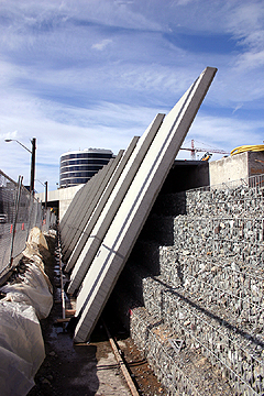
Wire mesh layered atop geotextile fabric creates a ‘basket’ for the drainage rock face of the mechanically stabilized earth system. The fascia panels, artistically sandblasted, overlap like armadillo armor to allow their movement and to avoid unsightly panel edge joints. |
Weiss/Manfredi’s envisioned journey ended with visitors able to physically touch the waters of Elliott Bay, a rare treat in a downtown with 8,000 feet of seawalled coastline. While a beach component existed from Day 1, so did questions about its permitability, given strict shoreline regulations.
As the park design team began coordination with city and state viaduct/seawall replacement designers, it became evident that 800 feet of seawall frontage within the park would someday need to be fixed.
The city/state team’s proposed fix was estimated at $50 million for the park frontage alone and would cause considerable disruption to park activities. While the city/state team had plans to fix the bulk of the seawall from behind, the park team bucked conventional wisdom that “putting stuff in the water” is forbidden and developed a rip-rap buttress system to support the seawall. The buttress design also included a habitat bench in the intertidal zone, for use during salmon migration.
Since the seawall buttress was integrated into the beach element to the north, all in-water work was permitted as a single shoreline restoration project. Regulatory agencies were thrilled with this voluntary restoration effort, and the seawall was repaired for $5 million — 10 times less than the city/state’s proposed approach.
Comparing results
Perhaps the best way to appreciate the impact of the park’s collaborative process is to imagine the park if traditional design methods had been used: massive, vertical-faced concrete retaining wall “tunnels” holding back excessive quantities of imported fill, accented by plain pedestrian bridges jutting up and over.
Now, go walk through the park and stop on the Elliott Avenue bridge … if you can even find it during your journey!
Drew Gangnes, P.E., is the director of civil engineering at Magnusson Klemencic Associates. He served as civil principal-in-charge on the Olympic Sculpture Park.
Other Stories:
- Park fits Seattle to a Z
- Sculpting an oasis from a blighted landscape
- Risky site inspired creative thinking
- Landscape grounded in Northwest natural history
- Complicated project packs a few surprises
Copyright ©2009 Seattle Daily Journal and DJC.COM.
Comments? Questions? Contact us.