|
Subscribe / Renew |
|
|
Contact Us |
|
| ► Subscribe to our Free Weekly Newsletter | |
Construction Bids
| home | Welcome, sign in or click here to subscribe. | login |


| |
 |
October 3, 2002
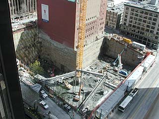
Photo courtesy of DBM Contractors At 97 feet, IDX Tower’s excavation was one of Seattle’s deepest. Two shoring walls were required to support the YMCA building, which forms a “reentrant” corner on the site.
|
The IDX Tower excavation extended as deep as 97 feet below Fourth Avenue, and supported the historic downtown Seattle YMCA.
The design of the shoring system was optimized by design modeling, and the performance was carefully monitored. Its successful performance opens doors to design changes that will result in more-efficient systems in the future.
Typical conditions, atypical site
Soils were typical for this area of Seattle, consisting of sand fill overlying interbedded silt, sand and clay. Except for the fill, all soils are overconsolidated and very dense or hard, although with some wet and unstable zones.
The site posed a number of challenges. First, the YMCA in the southeast quadrant of the block formed a “reentrant” corner, requiring two shoring walls for support. Second, the excavation was one of the deepest ever in the downtown core, and was further complicated by the relatively narrow streets on the east and north.
The variable fill, unstable clay soils, and unpredictable zones of groundwater have affected shoring design dominated construction performance in the downtown core from the first deep excavations completed in the 1960s. Various projects through the 1980s and 1990s have advanced the local design and construction practices, but the reentrant corner combined with the great depth of the hole is a combination only addressed a few times.
Shoring wall design
Conventional soldier piles and tieback anchors were selected for excavation support. The method consists of a W-section steel beam installed in a predrilled hole that is then filled with concrete. Tieback anchors are drilled into the soil adjacent to the soldier piles at angles of about 20 degrees below horizontal, affixed with locking pins, and prestressed.
Estimates of the lateral soil pressure envelope on deep excavation shoring walls are usually made using a combination of theoretical relationships and local experience.
Reentrant corner support
Tieback anchors passed within about two feet vertically of the bottom of the perimeter footings on the west side of the building, and as close as 4 feet to 8 feet below interior footings on the west and north sides. In addition, for about one-third of the wall the tiebacks were interfingered — with tiebacks from the west wall crossing those from the north wall. The design separation between the ties was two feet.
‘No-load’ zone modification
Along Fourth Avenue and the eastern half of Madison Street the street widths were not sufficient to allow construction of upper tieback anchors of traditional length. The no-load zone is an area of potentially yielding soil behind the shoring wall in which no anchors are allowed.
Skilling Ward Magnusson Barkshire developed a complete 3D computer model of the shoring system around the YMCA. The model reviewed the complex geometry of the soldier piles and tiebacks along this corner of the excavation. The model allowed soldier pile and tieback adjustments so that there were no conflicts.
Displacement-based analyses
Soil-structure interaction problems were modeled with a two-dimensional finite difference program called FLAC (Fast Lagrangian Analysis of Continua). The two key predictions from the FLAC model were displacements along the soldier pile and loads on the tieback anchors.
Carefully designed soldier pile/tieback walls rarely fail catastrophically. Rather, the failed tiebacks may cause them to deflect more than anticipated, resulting in ground surface settlement behind the wall, and potential distress to adjacent streets, utilities and buildings.
Thus, the relationship between tieback loads and soldier pile deflections predicted by FLAC is a critical check of the traditional design process. The FLAC model was based on input parameters from the site, and optimized using performance data from other sites.
Excavation monitoring
The shoring system was designed by Skilling and installed by DBM Contractors. It included 137 steel soldier piles at a maximum length of 112 feet. A total of 677 tieback anchors as long as 96 feet restrain the soldier piles, and 105,000 cubic yards of soil was removed by DBM over a five-month period.
During excavation, the performance of the shoring system was monitored using inclinometers, hydraulic load cells and optical surveys.
Inclinometer data were generally consistent with the predicted deflection shape of the FLAC analysis, although the actual deflections were slightly greater than the FLAC-predicted deflections, suggesting that the soil modulus values were slightly too stiff, and that the design soil pressures may have been too low for the planned deflection. It may also indicate that the effects of the reduced no-load zone and surcharge loads were greater than predicted by FLAC.
One conclusion drawn from the load-cell data is that the wall pressures were overestimated by an average of about 20 percent.
The optical surveys measured lateral deflections into the excavation, greater than 1/2 inch only along Fourth Avenue, the deepest part of the excavation and one of the areas with a truncated no-load zone.
Independent surveyors measured lateral deflections of about 1-1/2 inches in the middle of the block, and 3/4 inch to 1 inch near the corners. By comparison, lateral deflections on the west wall (Third Avenue) and the north wall (Madison Street) were 1/4 inch to 1/2 inch.
Street settlements were 1/4 inch around the site except along Fourth Avenue, where the settlements were 1 3/4 inches to 2 1/2 inches.
None of the shoring supporting or adjacent to the YMCA performed outside of the expectations of the design. Lateral deflections from the optical survey were less than 1/2 inch to 3/4 inches at the top, and that deflection did not result in distress to the YMCA.
New design criteria
David Winter is vice president of Shannon & Wilson, Inc., a national geotechnical and environmental consulting firm. He was principal-in-charge of the IDX Tower geotechnical program while at Hart Crowser, Inc. This article is a shortened version of a paper published by the Los Angeles Tall Buildings Structural Design Council.
Other Stories: