
DJC.COM
September 12, 2007
7 Engineering Wonders: Geotechnical — A firm foundation for the new Narrows Bridge
Shannon & Wilson
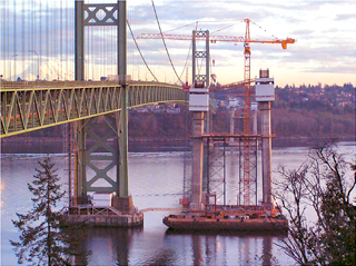
Photos courtesy of Tacoma Narrows Constructors/WSDOT The new Narrows Bridge was built just 200 feet south of the existing bridge. |
Complex stratigraphy, diverse topography, fault-zones, landslide-prone slopes, contaminated soils and endangered species. These are a few of the geotechnical and environmental engineering challenges faced in the Puget Sound area. Over the past 53 years, Shannon & Wilson has encountered many of these conditions, including one of our most notable projects — the new Tacoma Narrows Bridge.
Shannon & Wilson was part of the joint venture design team of Parsons Transportation and HNTB for the recently completed bridge. This team worked closely with the contractor, Tacoma Narrows Constructors (a joint venture of Bechtel and Kiewit), as well as the owner, Washington State Department of Transportation. The mile-long suspension bridge was constructed 200 feet south of the existing Tacoma Narrows Bridge in a narrow channel in Puget Sound.
Shannon & Wilson was responsible for the geotechnical and earthquake engineering studies for preliminary and final design of the bridge and approach structures. This was a design-build project with an aggressive schedule.
The bridge site was explored by performing borings and in-situ testing, including Oyo suspension logging and downhole pressuremeter tests. The borings for the caissons extended to about 200 feet below the mudline in more than 150 feet of water. Deep water, significant tidal changes and extremely fast currents (as high as 7 knots) complicated the explorations. Shannon & Wilson obtained all permits for the geotechnical borings on a fast track to accommodate fish closure windows.
The bridge is located at a very deep soil site consisting of sand, gravel, and silt glacial deposits. The depth of bedrock is estimated to be about 1,800 feet at the bridge site. The near-surface (upper 20 to 50 feet) soils are generally medium-dense to dense, while the materials deeper down are generally very dense, as they had been covered with about 3,000 feet of glacial ice. These very dense soils provide a good foundation for the bridge caissons and anchorages.
Caisson foundations
Caissons were selected during the conceptual stage of the project to support the bridge towers. They are 130 by 80 feet in plan and are embedded about 60 to 70 feet below the mudline into very dense glacial soils for a total caisson height of about 190 to 215 feet. The bottom 18 feet of each caisson includes a steel cutting shoe, which extends 6 inches beyond the upper concrete caisson to facilitate the sinking process. The cellular caisson has 15 interior dredge wells to enable the soil to be excavated from within the caisson so that it could sink to its final position. Once the required tip elevation was reached, the lower 25 feet of the caisson was filled with mass concrete to form a base seal.
Constructing caissons of this height and geometry were equivalent to constructing a 20-story reinforced concrete building below the waterline.
The design of the caisson and its depth of embedment was controlled by scour and earthquake loading considerations. The design team’s seismic specialists determined that allowing the caissons to rock about their base was an effective way of minimizing the seismic forces acting on the bridge. As a result, the design of the caisson exterior walls was controlled by two distinctly different loading conditions: water pressure and seismic.
During construction of the caisson, prior to touching down on the mudline, the caisson was floating and the exterior walls subjected to water pressure. The other loading condition occurs during a major seismic event. Extremely high soil pressures develop against the exterior walls as a result of the caisson rocking. We used the estimated movements of the caisson determined in the global seismic analyses to evaluate lateral earth pressure distributions acting on the caisson walls. Structural designers then used the resulting earth pressures to select the proper reinforcement and concrete member sizes of the caisson.
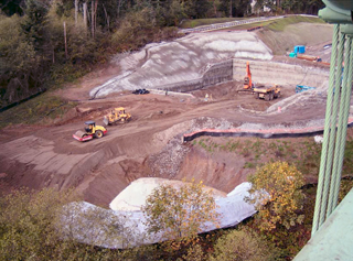
The bridge used conventional gravity anchorages, each weighing about 45,000 tons. |
Throughout the design of the project, the design-construct team was also concerned with the caisson sinking operation. Each caisson had to be sufficiently heavy to reach tip elevation, yet not be so heavy at touchdown that local instabilities would occur. A 5-foot-thick layer of riprap was placed along the dredged mudline to serve as a landing pad for each caisson. It was designed to prevent scour of the foundation soils and to provide a suitable foundation for the caissons at touchdown.
Analyses were performed to evaluate the caisson touchdown and sinking operations. There were two objectives:
• To estimate the penetration of the caisson cutting shoe upon initial touchdown under self weight.
• To evaluate the magnitude of the required dredging of the soil from the interior of the dredge wells to sink the caisson to its final depth.
The caissons were successfully constructed. They reached the design tip elevations and a 25-foot-thick base seal was placed to provide suitable foundations for the bridge towers. In general, few difficulties were encountered during construction. The caissons were advanced by controlled dredging around the interior of the dredge cells until they reached the required tip elevation.
Anchorages
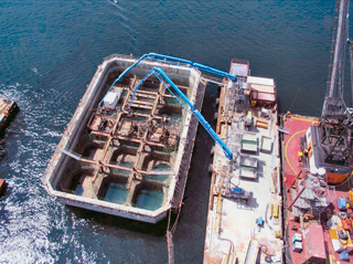
Each caisson has 15 interior dredge wells that were used for soil excavation. |
Conventional gravity anchorages were constructed on the hillsides adjacent to the Narrows to support each end of the bridge. The soil conditions at each anchorage location consist of 25 to 50 feet of medium to very dense granular soils, underlain by very dense silt, sand and gravel. Each anchorage is about 150 feet long and about 100-115 feet wide.
The anchorages are designed to accommodate a future lower roadway travel surface. Each anchorage has an estimated weight of 45,000 tons. The anchorages were constructed by excavating into the native soils and using a soil-nail system to retain the excavation sidewalls. Shannon & Wilson evaluated the stability of the anchorages and adjacent hillsides to assure adequate safety.
Design and construction of the new bridge presented challenging geotechnical engineering and earthquake considerations. These challenges were met by characterizing the subsurface conditions at the bridge site, by working closely with the design-construct team to develop solutions as the design evolved.
Both the caissons and anchorages have been successfully constructed and the new bridge opened July 16.
Gerard Buechel, PE, is the Seattle Office manager and president of Shannon & Wilson. For more than 27 years, he has performed engineering studies and managed many complex projects including transportation infrastructures, highways, railroad corridors, landslides, pipelines, residences on steep slopes, embankments and dams on soft soils, high-rise structures and large industrial facilities.
Other Stories:
- A beautiful tomorrow for structural engineering?
- 7 Engineering Wonders: Structural — How to keep it all working after the BIG ONE
- Infrastructure: out of sight, out of mind?
- Engineering a sea change at the aquarium
- ACEC says ‘yes’ to roads and ‘no’ to lawsuits
- Engineers, architects join forces on public policy
- Is our engineering rank slipping in the world?
- 7 Engineering Wonders: Electrical/Communications — Engineering a hospital to save lives
- 7 Engineering Wonders: Mechanical — EMP: an experience unlike any other
- 7 Engineering Wonders: Environmental — Brightwater planning raises awareness, not eyebrows
- 7 Engineering Wonders: Transportation/Infrastructure — Tunnels keep traffic flowing out of sight
- 7 Engineering Wonders: Civil — Making the grade for a road separation
- Geotechnical engineering gets a tech boost
- Finding workers may be engineering’s biggest challenge
- ACEC members pick the best of 50 years
- What a difference 50 years make
- What makes engineers tick?
Copyright ©2009 Seattle Daily Journal and DJC.COM.
Comments? Questions? Contact us.