|
Subscribe / Renew |
|
|
Contact Us |
|
| ► Subscribe to our Free Weekly Newsletter | |
| home | Welcome, sign in or click here to subscribe. | login |
Construction
| |
 |
May 9, 2014
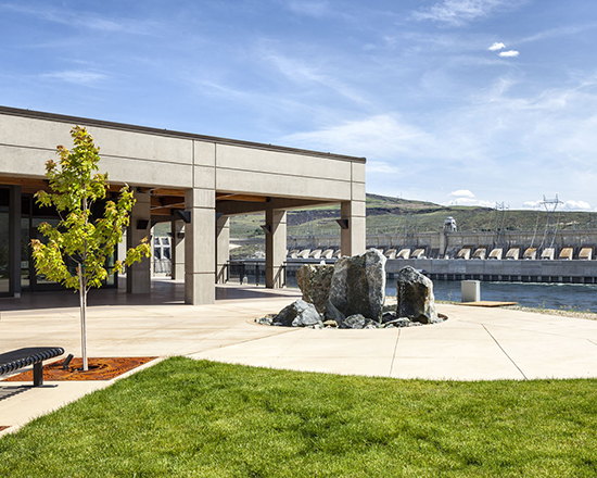
Chief Joseph Fish Hatchery
GRAND AWARD WINNER
PUBLIC WORKS: CIVIL PROJECTS (TIE)
Location: Bridgeport
Owner/developer: Bonneville Power Administration
Project team: PCL Construction Services, general and concrete contractor; Tetra Tech, architect and structural engineer; Godbey Red-E-Mix, ready-mix supplier
The Chief Joseph Fish Hatchery involved four different construction sites spread out over 40 miles in rural north-central Washington.
The state-of-the-art hatchery is fully sustainable from a fish culture standpoint and can raise 2.9 million chinook salmon per year.
The facility was designed and constructed with two focuses: automation and low-maintenance durability. Various systems can be monitored remotely with minimal staff and were designed to survive harsh summers and winters.
Ready-mix concrete was used throughout the project.
Nearly 9,000 cubic yards of concrete were used during construction. Concrete elements included two separate in-water pump stations on the Okanogan River; a fish ladder and broodstock facility in the Columbia River; two banks of 20 fish raceway cells; five fish acclimation and rearing ponds with concrete inlet and outlet structures; a concrete tilt-up hatchery building; a waste facility; a storage building with cast-in-place walls; a process water headbox; an office building with exposed concrete beams, walls and polished concrete floor; a colored concrete plaza; and an intake bulkhead 50 feet below water at Chief Joseph Dam.
Although concrete was necessary throughout the entire facility for its durability, concrete was essential for one technical element. Approximately 60 percent of the water supplied to the facility was to be from a gravity-fed pipeline with a steel intake bulkhead. However, divers discovered that the adjacent riprap embankment was unstable and had the potential to damage the steel gate and break the watertight seal of the system.
With the project already under construction when this was discovered, the project team worked together quickly to design a concrete intake wall that could be constructed underwater in lieu of the original steel intake bulkhead.
Using concrete eliminated the fears about riprap damaging the intake area. It also eliminated the need to inspect the intake system with divers on a regular basis. (The U.S. Army Corps of Engineers requires yearly inspections for underwater steel structures). Concrete solved the immediate construction needs and reduced substantial long-term maintenance costs.
Placing a concrete intake wall underwater did however present a significant number of challenges that the team needed to work through.
While the engineer worked on the design of the permanent structure, the general contractor worked with the project divers to design a formwork system as well as a protective shield to keep divers safe from the riprap that rolled down into the area during construction of the wall.
The wall was placed using bottom-up concrete placement with a one-of-a-kind concrete mix specially designed for the project. Additionally, a Fuko water stop system was cast into the wall and injected after curing with a hydrophilic water stop compound.
With large concerns about this kind of placement (from the concrete mix to the underwater pumping method) and achieving proper consolidation, the team constructed a mock-up wall in one of the fish raceways. A test wall was cast underwater using the same size pump truck and attachment systems that would be used on the actual wall. Thanks to everyone’s effort and teamwork, the wall placement went off with no issues and provided a watertight seal that exceeded expectations.
Other Stories:
- Revised structural concrete ‘cookbook’ will follow a simpler recipe
- Liberty Lake roundabout
- Cascade Middle School
- Estancio I
- Grand Ridge Plaza blocks 2, 3, 17 and 18
- Hendricks residence
- Diamond S Ranch
- Lower Baker Unit 4 Powerhouse
- Satus Creek Bridge replacement
- Husky Stadium renovation
- Clearwater Casino parking garage
- Providence Medical Office Building at Hawks Prairie
- The Martin apartments


